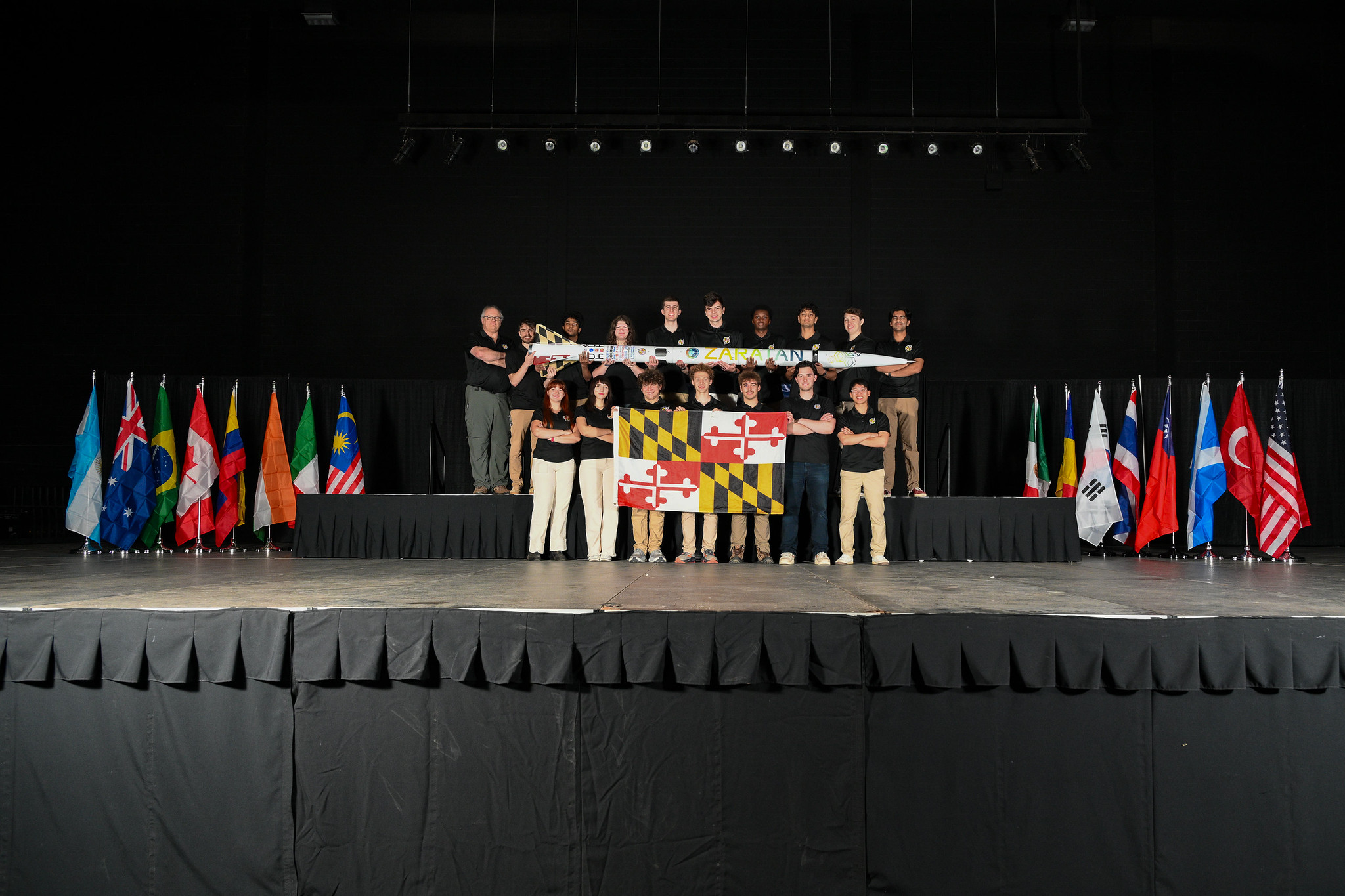
Terrapin Rocket Team on stage with their rocket and the Maryland flag

Projects.

2027 airbrake development.

Live · In progress

A new cycle of airbrake development for the Terrapin Rocket Team. I’m leading the work across mechanical design, CAD, and controls, building on the prototypes and flight experience from 2026.

The work brings together deployment hardware, electronics thermal management, and telemetry-driven control.

  1. Sep 2025 – May 2026

    Design, build, fly

    Seven generations of L1 airbrake prototypes, Teensy-based control hardware, and an H100 flight test.

  2. June 2026

    IREC flight experience

    Flight software integrating Blue Raven telemetry contributed to the team’s ~20,000 ft club altitude record.

  3. Current · 2027 development

    The next system

    Leading design direction, mechanical development, controls, and preliminary design reviews.

  4. Next · planned

    Prototype & validate

    Build and test the next iteration. Milestone dates and results will be added as the work progresses.

Carbon-tube aero mounts.

Live · Research & concept development

A new Terps Racing side project exploring bonded metal inserts for carbon-fiber aero mounting tubes. I’m investigating adhesive selection, bond-line clearance, and insert surface geometry before developing a batch of test specimens.

The starting point is the team’s custom Goodwinds tubes and current 3M 460 epoxy. Planned work includes lathe-machined inserts, milled clevises, and external testing in Baltimore to compare joint designs. Strength and suitability will be established through testing.

  1. September 2026 · Current

    Research the joint

    Review adhesive options, tube data, insert geometry, and the effect of bond-line thickness. Establish test requirements with the team.

  2. Next · Planned

    Design & machine

    Develop insert variants for the lathe and plan the clevis milling operations.

  3. Planned

    Build a test batch

    Prepare bonded carbon-tube specimens to compare the proposed joint geometries and adhesive approaches.

  4. Planned

    Test & refine

    Send specimens for external testing in Baltimore, review results, and refine the aero-mount design.

Completed projects.

Rocketry, Formula SAE, and personal projects. From first geometry to prototypes, test data, and working hardware.

Formula SAE

Mini aerodynamic validation wind tunnel

A modular tunnel for turning CFD questions into visible airflow.

01

Terps Racing EV · Test equipment

Mini aerodynamic validation wind tunnel

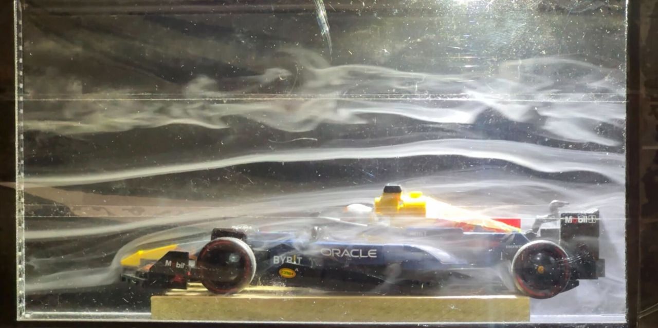
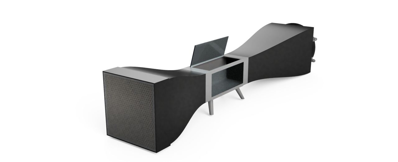
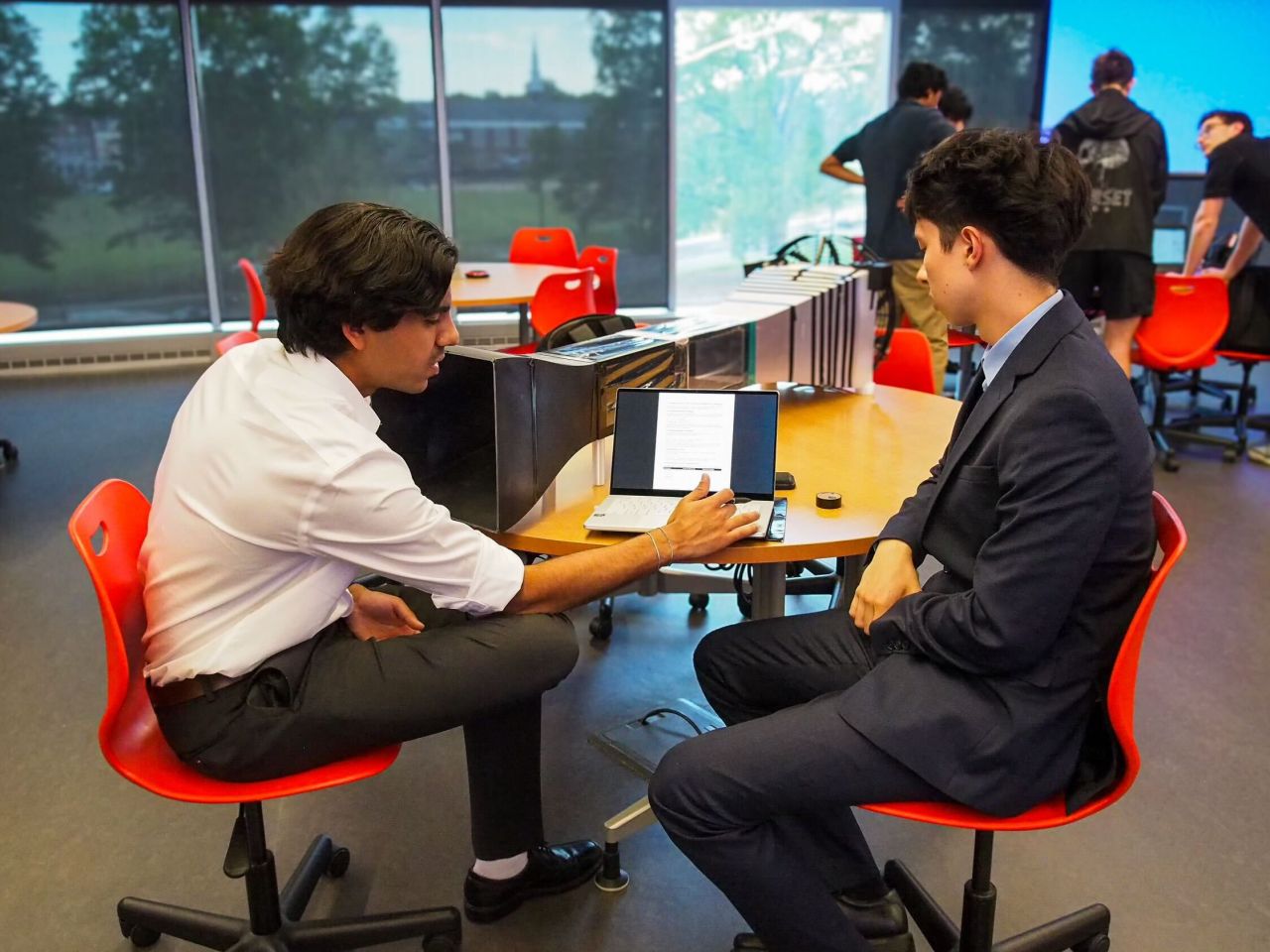
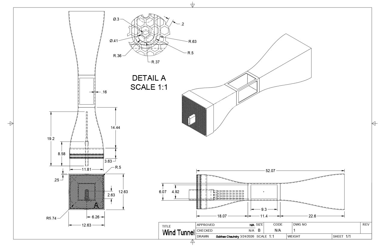
A modular, desktop-scale wind tunnel built to compare aerodynamic designs with physical flow visualization. A honeycomb straightener and 4.23:1 contraction feed the test section, with a PWM-controlled 120 W axial fan drawing air through the system. Steam testing informed a transition to smoke visualization; the tunnel supported evaluation of four undertray iterations.

4.23:1Contraction ratio
120 WAxial fan
4Undertray iterations
Design report

Modular by design

Segmented PLA construction with magnetic connections makes sections replaceable. Removable honeycomb and mesh simplify maintenance; single and dual test-section layouts allow different setups.

Flow conditioning

Early ultrasonic mist was too thin for clear visualization. Smoke testing, followed by the aluminum honeycomb and mesh screen, produced clearer, more structured streamlines.

Sizing the drive

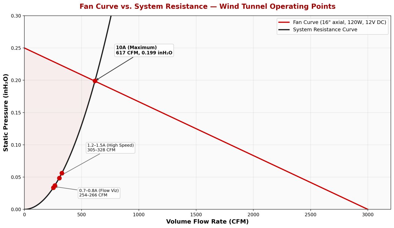
The fan curve and system resistance analysis predict 5.7–5.9 m/s at the standard visualization setting. These are calculated operating points, not measured velocity results.

From concept to test section.

  1. January – February

    Brainstorm & design

    Explore the tunnel layout, component requirements, flow conditioning, and fabrication approach.

  2. March

    First fabrication

    Build and connect the first components, including the frame and fan assembly.

  3. April

    First two tests

    Run the first tests and use steam visualization to study the flow and refine the setup.

  4. Late April – early May

    Test & document

    Test different aerodynamic components, complete the project, and consolidate the design documentation.

The tunnel supports qualitative flow comparisons. It has no force balance, so these tests do not directly measure lift or drag.
Rocketry · Personal flight hardware

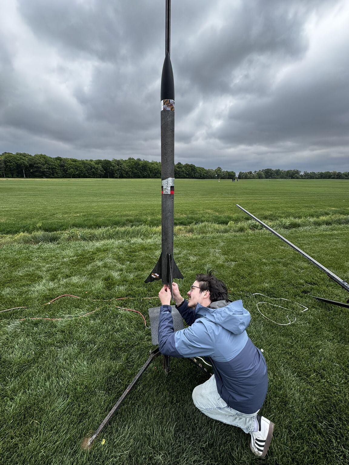
Alternative L1 Airbrake

Seven prototypes. One flight. A new iteration ahead.

02

Rocketry · Personal flight hardware

Alternative L1 Airbrake

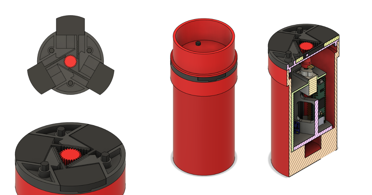
A compact alternative to a conventional lead-screw airbrake, developed from iPad sketches through seven prototypes. Three gear-driven flaps deploy radially from a flush 3-inch airframe. The first H100 flight delivered a full ascent dataset—and a clear direction for the next launch.

7Prototypes
80%Less deployment profile area
50%Shorter overall

A different mechanism

A servo-driven central pinion moves three flaps laterally, replacing the competition system’s lead screw and L-profile deployment. Iteration focused on flap geometry, local reinforcement, and packaging electronics. FEA checked the final structure under deployment and aerodynamic loads.

Prediction on board

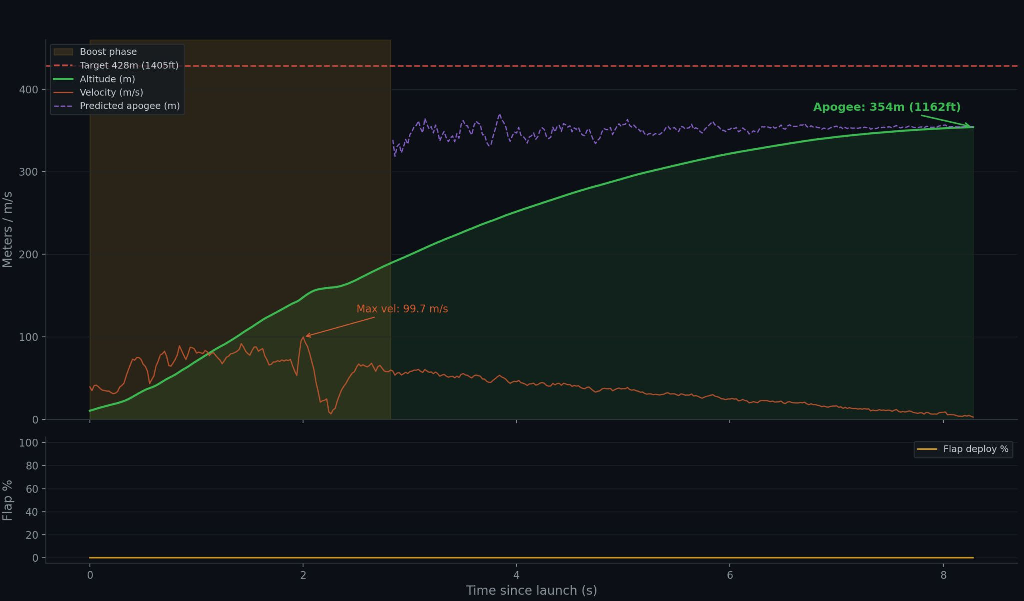
A Teensy and BMP388 sample at 20 Hz. My software combines exponential moving-average filtering, real-time CdA estimation, and a Heun RK2 integrator with an ISA atmosphere model to predict apogee and choose between deployment and retraction against a 428 m target.

The flight—and what comes next

The MDRA L1 certification attempt reached 354 m (1,162 ft), with a maximum velocity of 99.7 m/s. Flap deployment stayed at 0%, and the parachute ejection charge failed, resulting in a lawn-dart landing. The airbrake and flight computer survived. A damaged servo and depleted battery are suspected contributors to the lack of actuation; I plan to address them and fly again next semester.

The project timeline.

  1. September – fall

    Brainstorm & prototype

    Sketch the lateral mechanism and iterate through 3D-printed designs.

  2. Winter – spring

    Code & manufacture

    Integrate the printed mechanism, avionics, prediction software, and structural checks.

  3. Spring

    Launch & collect data

    Fly on an H100 at MDRA and recover a complete ascent dataset despite the failed parachute deployment.

  4. By May & next steps

    Analyze & improve

    Review the flight, investigate power and servo issues, and prepare for another launch.

Terps Racing IC · Aerodynamics

Aero helmet redesign

A real helmet, rebuilt as a more representative simulation model.

03

Terps Racing IC · Aerodynamics

Aero helmet redesign

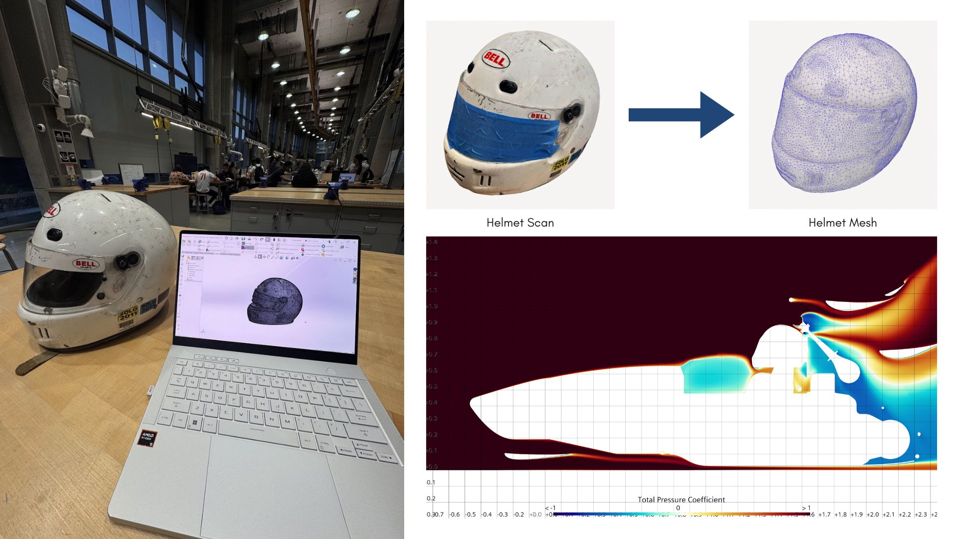
I updated a helmet subassembly that had gone nearly a decade without a redesign. An iPhone LiDAR scan became a cleaned and accurately scaled SolidWorks model, then part of the full car assembly for my first STAR-CCM+ simulation.

LiDARScan to mesh
500CFD iterations
8 hSimulation time

From scan to assembly

I captured a real helmet with my iPhone’s LiDAR scanner, cleaned and simplified the mesh in SolidWorks, then scaled it to the competition helmet and integrated it into the car’s CAD assembly.

A first CFD campaign

After roughly 90 minutes learning the setup, I ran 500 iterations over nearly eight hours on Jarvis, a Terps Racing high-workload system. This was my first experience with STAR-CCM+, 3D scanning, and meshing.

A better model for analysis

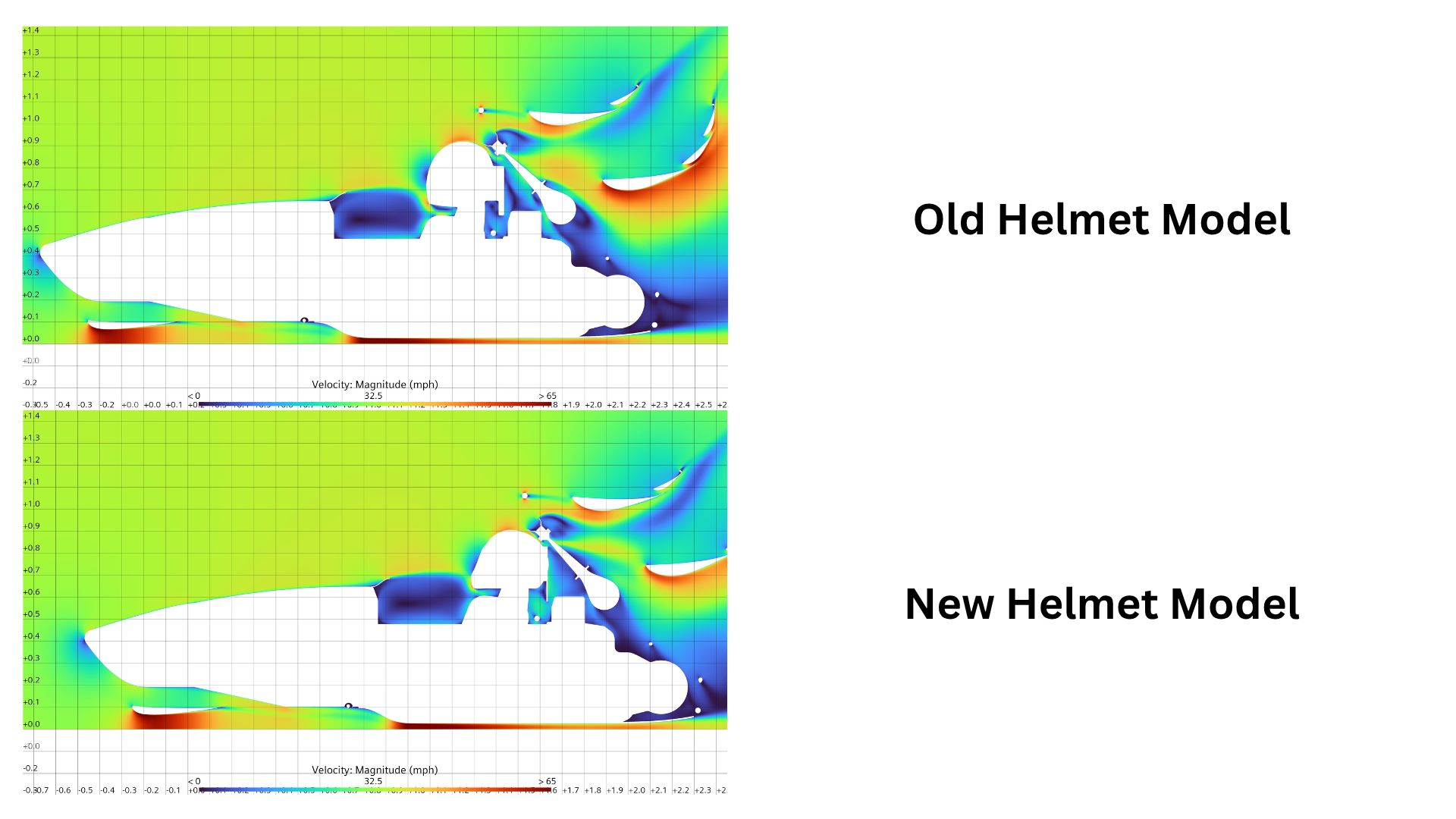
The updated simulation showed smoother airflow and reduced turbulence around and behind the helmet assembly. The goal was a more representative aerodynamic model; the comparisons shown here document the simulation work.

The project timeline.

  1. Capture

    Scan the helmet

    Use iPhone LiDAR to capture the geometry of a real helmet.

  2. Rebuild

    Clean & scale

    Simplify the mesh in SolidWorks and match the competition helmet’s dimensions.

  3. Simulate

    Run on Jarvis

    Integrate the assembly and run the STAR-CCM+ simulation for 500 iterations.

  4. Evaluate

    Compare the wake

    Review the old and new model results to improve the fidelity of future aerodynamic analysis.

Personal · Embedded systems

OPTML transit optimiser

Less waiting on the platform. Better timing from the dorm.

04

Personal · Embedded systems

OPTML transit optimiser

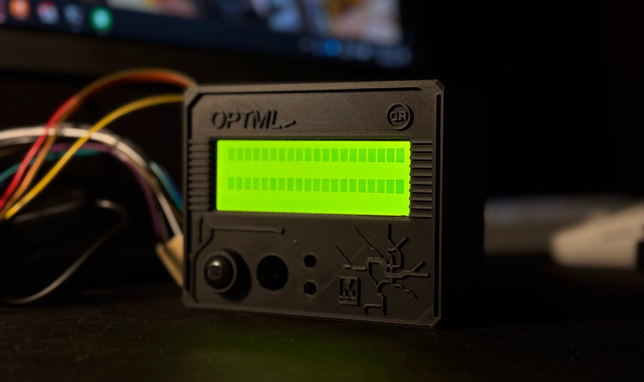
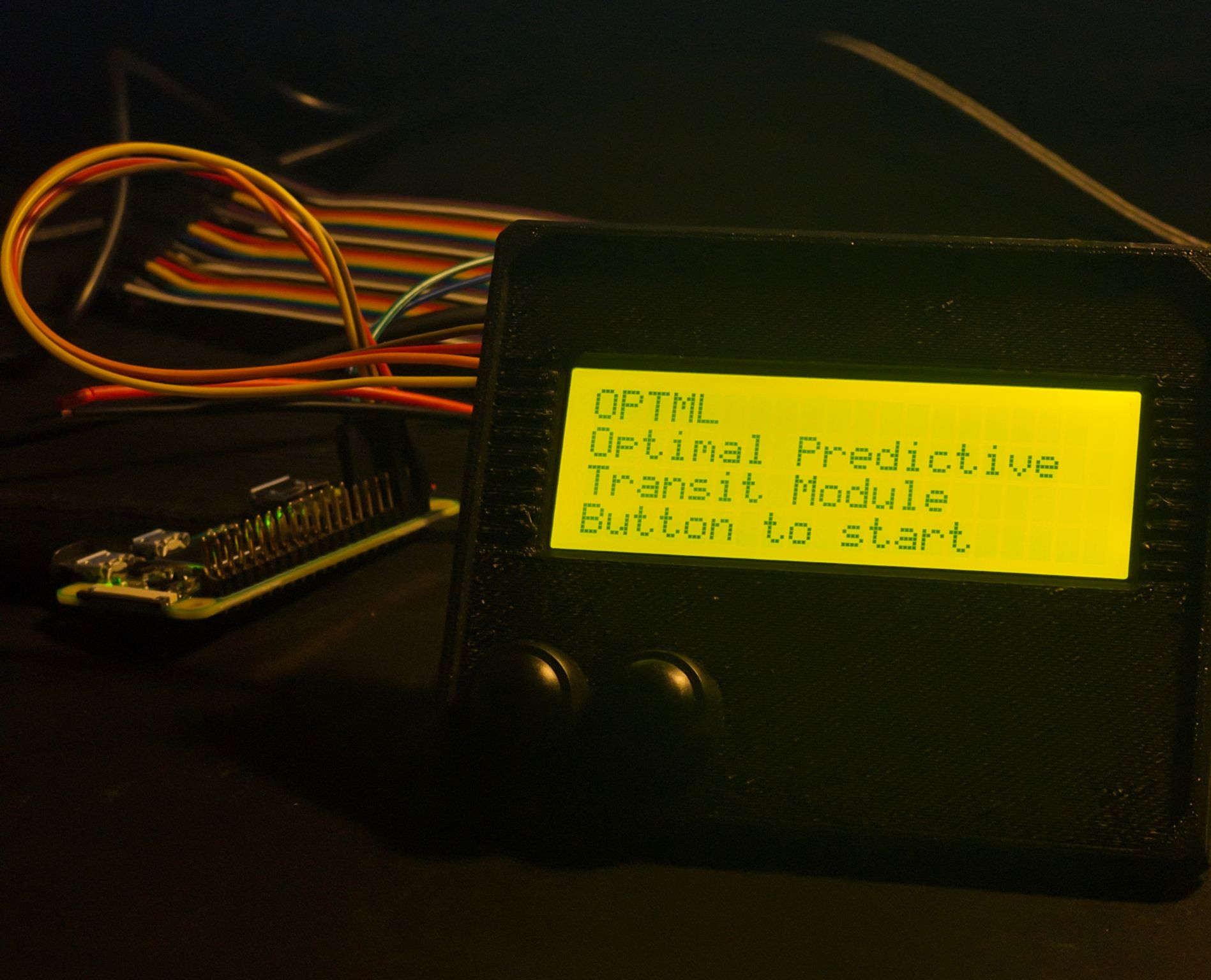
Optimal Predictive Transit Module: a Raspberry Pi device that combines WMATA Green Line and Shuttle-UM 104 arrival data to find a good time to leave my dorm. Instead of arriving to a long wait, the goal is to meet a train with one to two minutes of slack.

20 sData refresh
1–2 minArrival slack
104Shuttle-UM route

Two services, one decision

The device refreshes train and bus arrival data every 20 seconds. An OPTIMAL display mode and an audio cue from dual speakers identify a useful departure window; WAIT and GO modes provide alternatives when an optimal connection is not available.

Built for imperfect data

WMATA’s live arrival feed accounts for service delays. A stored Route 104 schedule provides a fallback when the Shuttle-UM API is unavailable.

From electronics to everyday use

The working device brings together the Raspberry Pi, display, speakers, and a 3D-printed enclosure. I’m refining the enclosure and polishing the code, with testing planned for the next semester.

The project timeline.

  1. December

    Define the commute

    Map the dorm-to-Metro trip and connect the train and bus arrival feeds.

  2. January

    Build the module

    Develop departure-window logic and integrate the display and audio cues.

  3. February

    Refine the prototype

    Iterate on the printed enclosure, code, and schedule fallback.

  4. Next semester · planned

    Test in daily use

    Evaluate real commuting connections and refine the timing.